LRC AC Circuits
Previously, we have examined circuits with either capacitors and resistors or inductors and resistors powered by batteries that produce constant voltage. These are called direct current (DC) circuits. When a switch was closed to complete a circuit, the current varied in time, and the time dependence was exponential (the current had a term ).
If we use a voltage source that varies in time sinusoidally instead of a battery, the current will also vary in time sinusoidally, possibly with a different phase. There will also be a “transient” exponential variation for a short amount, but here we only discuss the variation after the transient variation is zero “steady state.”
Figure (a) below shows a circuit in which an AC power source causes the current to vary sinusoidally in time according to . By Ohm’s law, the equation for the instantaneous voltage across the resistor is , where is the amplitude of the voltage source.
Figure (b) shows the time variation of current and voltage for this circuit. The voltage and current are “in phase” because the peaks, valleys, and zero crossings of and occur at the same time.
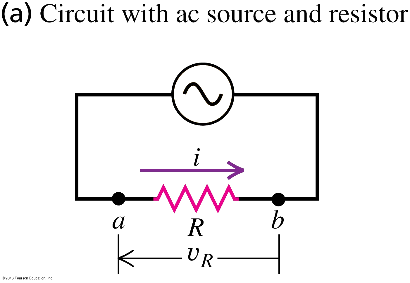
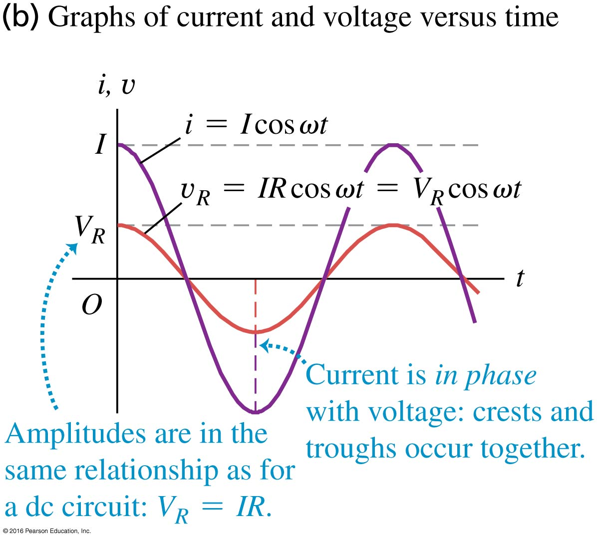
Figure (a) below shows a circuit in which an AC power source causes the current to vary sinusoidally in time according to .
The voltage across the inductor varies in time according to .
The term is called the inductive reactance: , which has units of when has units of and has units of . With this new variable, .
Figure (b) shows the and . The voltage across the inductor “leads” the current by (or, equivalently, , where ) because the maxima (or minima) in occur before the maxima (or minima) in .
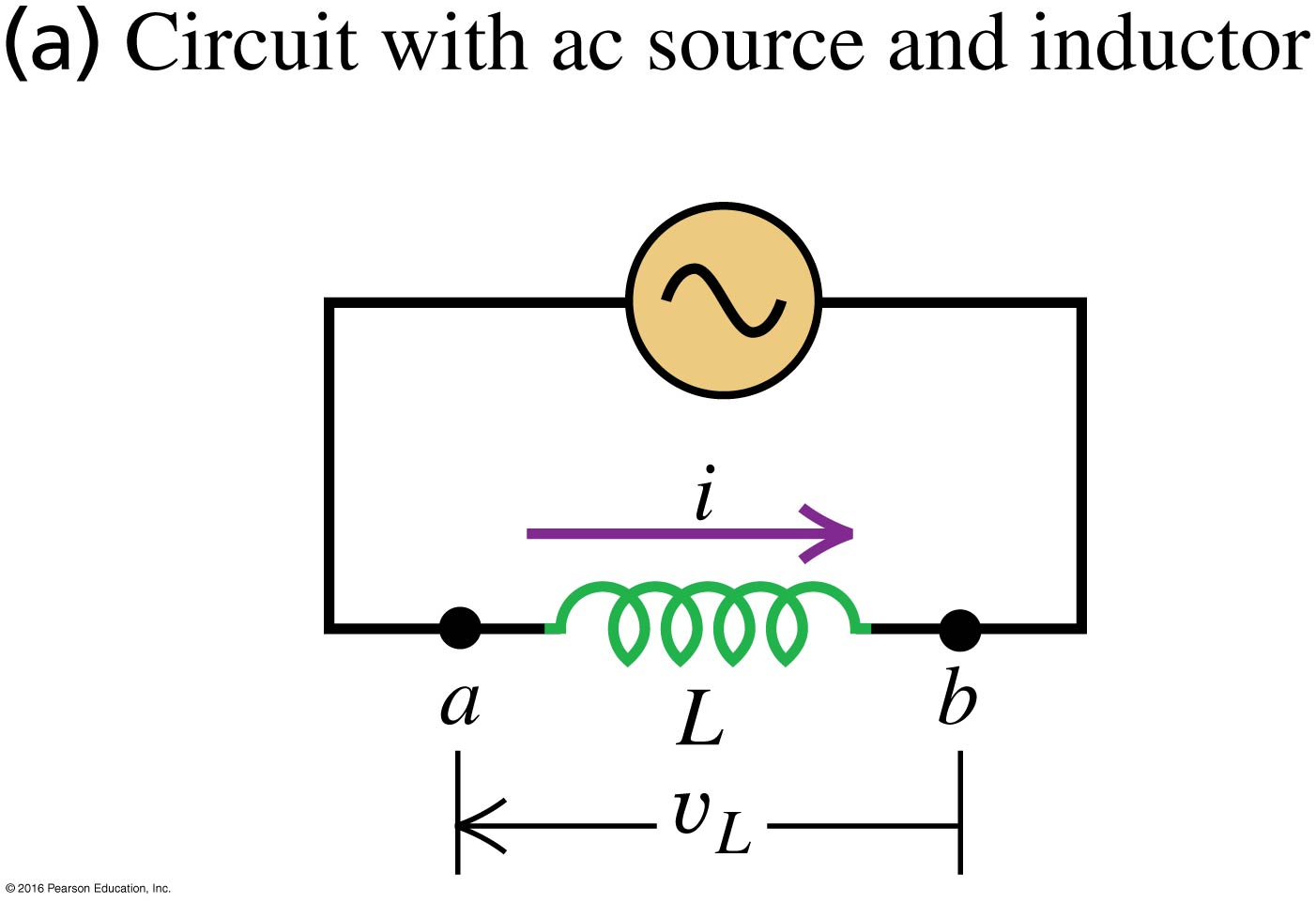
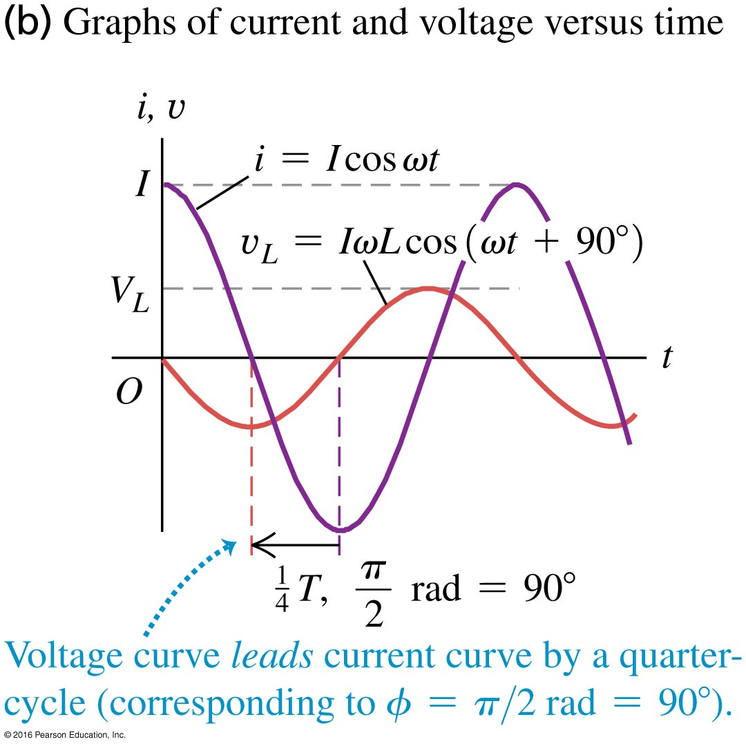
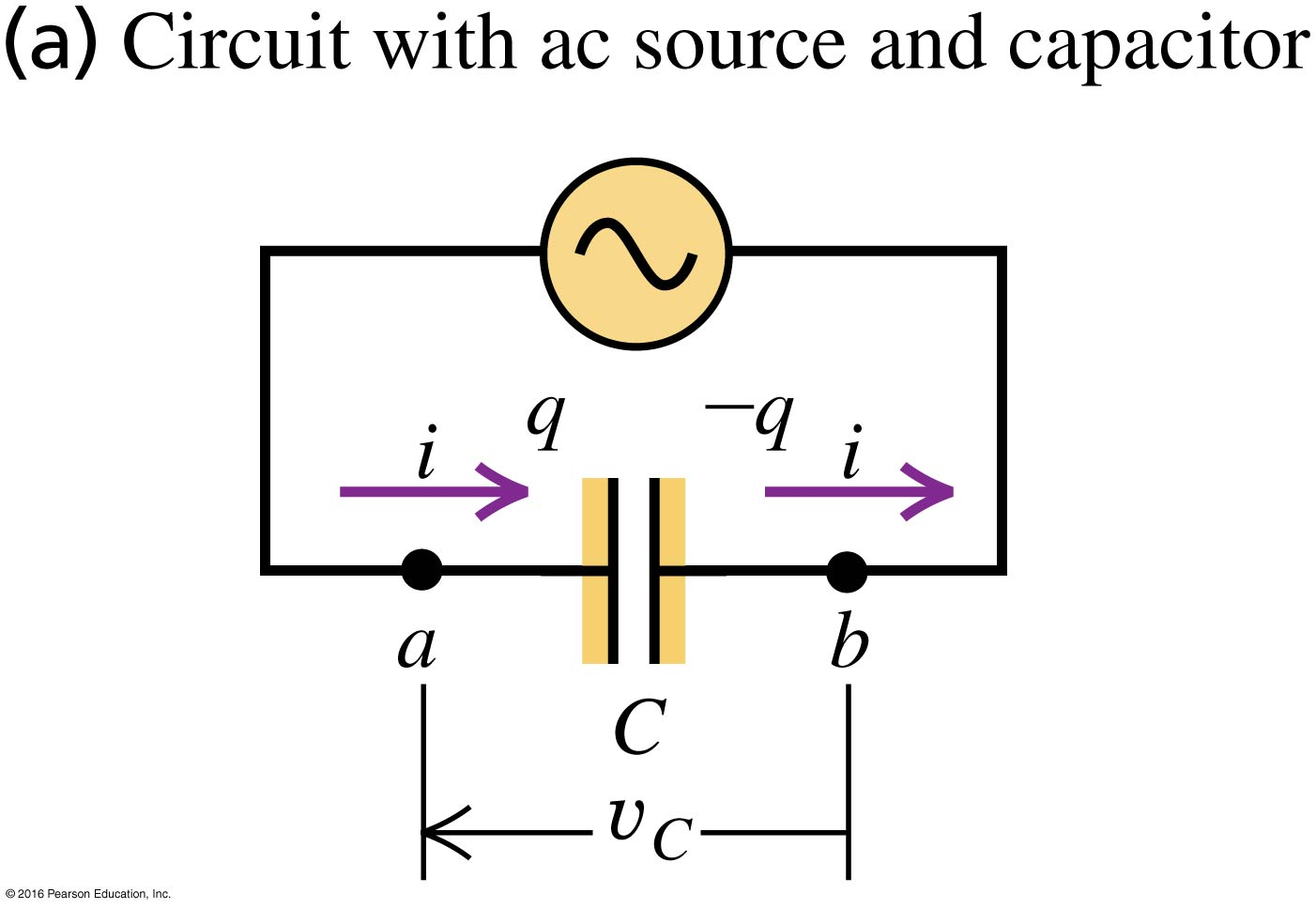
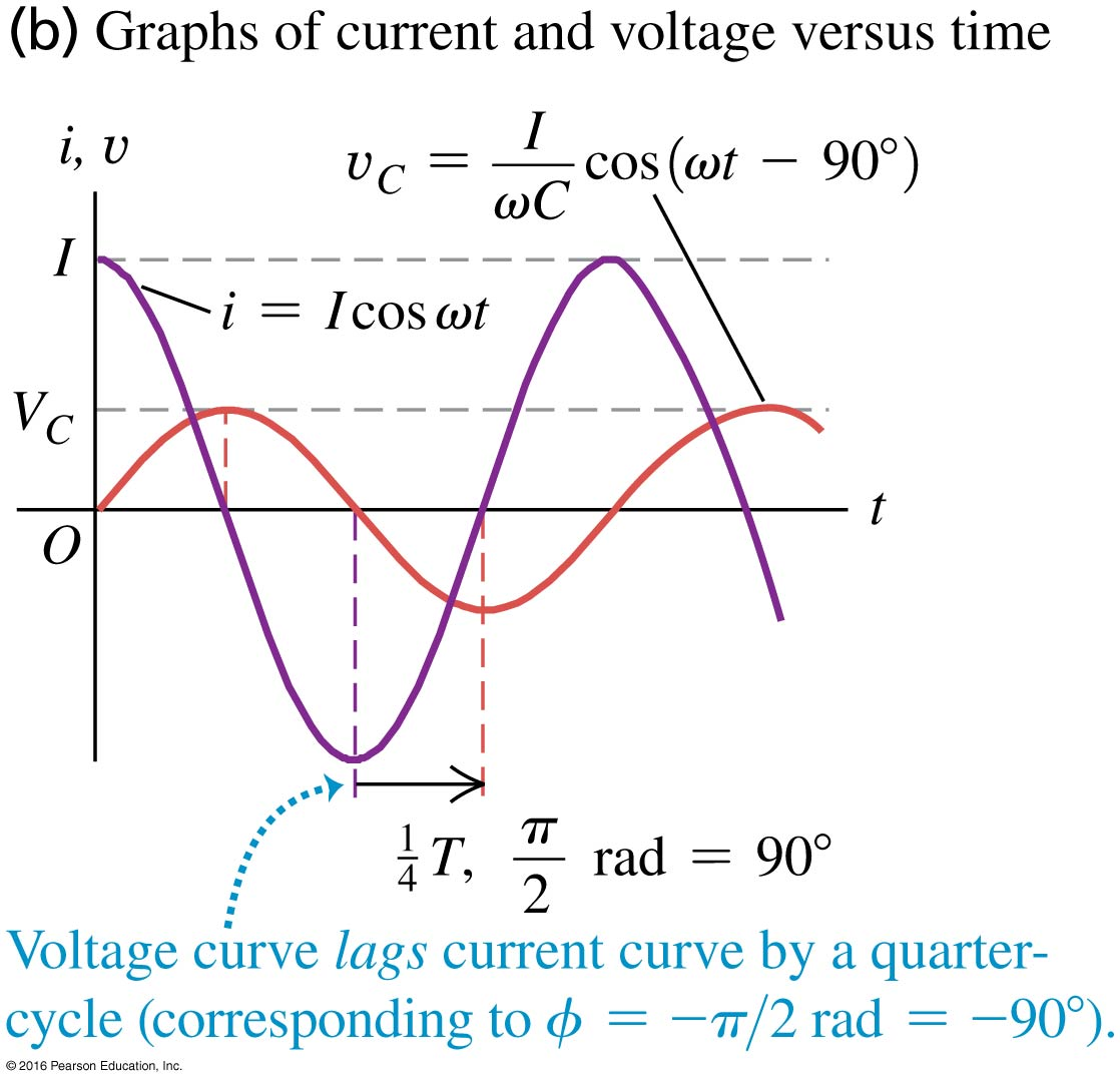
Figure (a) below shows a circuit in which an AC power source causes the current to vary sinusoidally in time according to .
The voltage across the capacitor varies according to .
The term is called the capacitive reactance: . With this new variable, .
Figure (b) shows the and . The voltage across the inductor “lags” the current by (or, equivalently, ) because the maxima (or minima) in occur after the maxima (or minima) in .
Suppose that we know the current in the following series LRC circuit is .
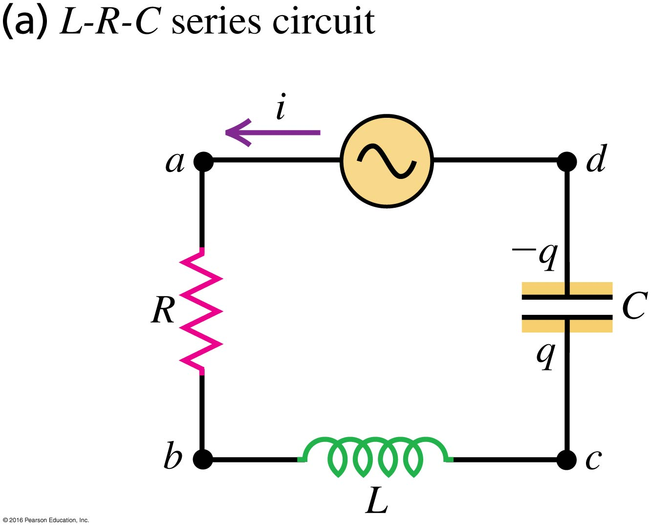
We want to know the voltage across the AC power supply, , which we call . We know the voltage across each of the components from the discussion above:
From Kirchhoff’s voltage law:
Substitution gives
In this activity, you will compute in two ways. First, you will use the above formula and a trig identity to write in the form , where the constants and depend on , , and (or equivalently, , , and ). Next, you will use a general formula to compute and .
A series LRC circuit with known values of , , , and are such that , , and . In addition, assume and .
Plot all quantities requested below on the same graph.
-
Plot
Answer: See Desmos plot
-
Compute the period, , of
Answer: There are two ways to answer this.
-
The current is .
-
At , .
-
When , again for the first time.
So the time for the to return to its starting value is such that .
-
-
Using the formula .
-
-
Plot , , and
Answer: See Desmos plot. Note that when . To get in the Desmos plot, we set .
-
Starting with , use the trig identity
to write in the form .
That is, find the constants and .
Answer: Here we have , , and , so
.
This matches the given identity if , so
.
Because of the , we say that leads by (or or ).
-
Plot
Answer: See Desmos plot. Adjust the parameters , , and to see how they change the curves (amplitudes and phases).
In the previous problem, computing required the use of a trig identity to combine and and write in the form , where and are constants that depend on and . When is not zero, additional algebra is needed to compute (by using the trig identity again). However, there is a formula that can be used to find in general so that trig identities are not needed.
It can be shown that in general, the voltage across the AC power source in a RLC circuit when is
Where the series LRC impedance is defined as
and
When is positive, leads . When is negative, lags . When , is in phase with .
-
Using the parameters given in the previous problem, find using the above formula.
Answer: In the previous problem, we were given , , so . Thus
and
Thus,
which is the same as found in the previous problem.
-
Suppose is not zero. What is the relationship between , , and such that the voltage and current in the circuit is in phase?
Answer: The voltage varies according to , where .
The voltage is in phase with the current, which varies according to , when . This requires
, or .